Electronic Password Lock System
A combination lock built on a Xilinx FPGA, written in VHDL and developed in Vivado. Entry comes from a 4×4 matrix keypad; everything the lock says back goes out on a multiplexed seven-segment display driven straight from the fabric. It holds several user passwords alongside one administrator password, and three wrong entries in a row latch an alarm that only the administrator can clear.
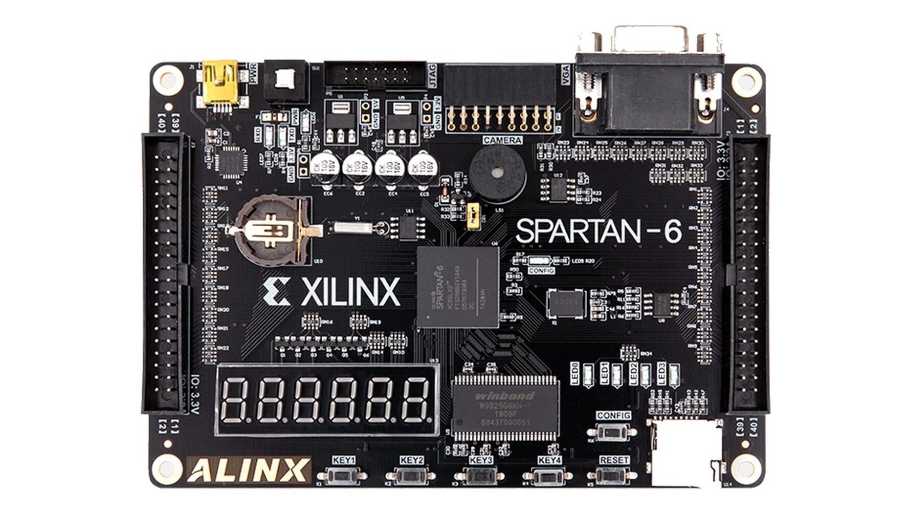
The board carries a six-digit display, an indicator row and the expansion headers. The keypad is not on it: a 4×4 matrix module is wired to the headers on the right-hand edge, eight lines for sixteen keys. That is the whole external interface, and it is the reason the scanner has to be part of the design rather than something the board hands over ready-made.
What the lock does
The behaviour is small enough to state completely, and stating it completely is what made the rest of the design fall out. The lock accepts a digit at a time from a sixteen-key pad and shows what it has taken on a six-digit display. It holds several user passwords and one administrator password, and it distinguishes between them: any user password opens the lock, the administrator password opens it and also reaches the state where passwords are set. A new password is taken twice and committed only when the two entries agree. Three wrong entries in a row latch an alarm, and the alarm has exactly one way out—the administrator password. What has been set survives a power cycle.
Everything on this page is that list turned into hardware. The interesting part is not any single capability but the fact that they are all consequences of one graph, so no capability can be satisfied and then quietly undone by another.
Everything runs at once
On a microcontroller a lock like this is a main loop that scans the keypad, refreshes the display and decides what to do, one after another. On an FPGA there is no loop. The keypad scan, the display multiplexer and the lock's own logic are three pieces of hardware running at the same time, each on its own tick from a divider chain off the system clock.
That is the design, not an implementation detail. The entry logic never waits on the display, so a key press cannot be missed because a digit was being refreshed; the display never waits on the lock, so it stays lit and steady while a password is being compared. Each of the three has one job and one rate, and the interface between them is a handful of registers.
Four blocks, four rates, one direction of data between them:
- Divider chain. One counter off the system clock, tapped at several points. Every other block takes its tick from a different tap, so the rates are fixed by wiring rather than by anything that could be recomputed at run time.
- Keypad scanner. Drives one row at a time, samples four columns, debounces by agreement across consecutive passes, and emits one event per press. It hands the entry logic a stream of key events, never a picture of which keys are down.
- Entry and state logic. Accumulates digits, compares against the stored set, and owns the state register. It is the only block that decides anything.
- Display multiplexer. Lights one digit at a time from a register the state logic writes, and never waits on it.
Reading the keypad
Sixteen keys reach the FPGA on eight wires. The scanner drives one row low at a time and reads the four columns, so the row being driven and the column reading low together name the key. The scan runs on a divided clock slow enough that a mechanical contact has stopped bouncing by the time it is sampled, and a key counts only when the same column reads the same way on consecutive passes.
A key is then registered once, on the edge, rather than for as long as a finger stays on it. Holding a key produces one digit. That single decision is what keeps the entry logic downstream simple: it receives a stream of key events, not a picture of which keys are currently down.
Driving the display
The lock has no screen and no serial port, so the seven-segment display is the whole of its language. The decoder covers the digits and the letters, which lets the same display carry an entry and a state without a second indicator.
The digits are multiplexed: one is lit at a time and the set is cycled fast enough to read as continuous, with the segment bus blanked between digits so one digit's pattern is never briefly visible on the next. The multiplexer runs off its own divider and does not stop for anything the rest of the design is doing.
The state machine
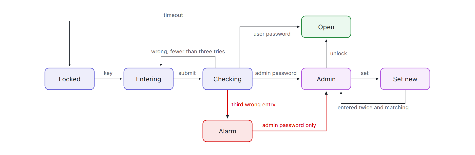
The lock proper is one state machine, and every capability it has is a transition in it. A key press moves it out of Locked into Entering, where key events accumulate. Submitting the entry moves it to Checking, and what happens next is decided by the comparison.
The comparison does not produce one bit. It produces two: whether the entry matched a user password, and whether it matched the administrator password. Keeping those separate is what makes the rest of the machine work. A user password opens the lock. The administrator password opens the lock and reaches the administrator state, where passwords can be set and changed.
A wrong entry increments the attempt counter and returns to Entering. The third one moves the machine to Alarm, which is a latched state: the only edge leaving it is guarded by the administrator bit. A user password does not clear it, retrying does not clear it, and letting the counter roll over does not clear it, because none of those is the transition that exists. The property the lock is supposed to have is the shape of the graph rather than a rule enforced somewhere in the logic.
One entry, end to end
A single attempt passes through every block in order, and following it is the shortest description of the whole design:
- A finger closes one contact. The scanner is driving row 2 at that instant; column 3 reads low; the pair names the key. The contact is still bouncing, so nothing is emitted yet.
- On the next passes the same column reads the same way. The scanner declares the key, emits one event on the edge, and does not emit again no matter how long the finger stays down.
- The entry logic appends the digit and writes the display register. The multiplexer picks the change up on its own tick; the lock does not wait for the digit to become visible.
- Submit moves the machine to Checking. The entry is compared against the whole stored set at once, producing two independent bits: matched a user password, matched the administrator password.
- Those two bits pick the next state. User opens the lock; administrator opens it and unlocks the setting state; neither increments the attempt counter and, on the third failure, moves to Alarm.
Nothing in that sequence is a decision made in more than one place. The scanner decides what a press is, the comparison decides what an entry matched, and the graph decides what follows— which is why the alarm cannot be cleared by anything except the edge that exists for it.
The passwords
User passwords are held together with the administrator password, so checking an entry is a comparison against the set rather than against a single register, and setting or changing one writes a single slot and leaves the rest untouched. A new password is taken twice and committed only when the two agree, so a mistyped password cannot lock its own owner out. What has been set is written to the board's flash, so a power cycle brings the lock back configured rather than back to a default.