Enterprise Network Simulation
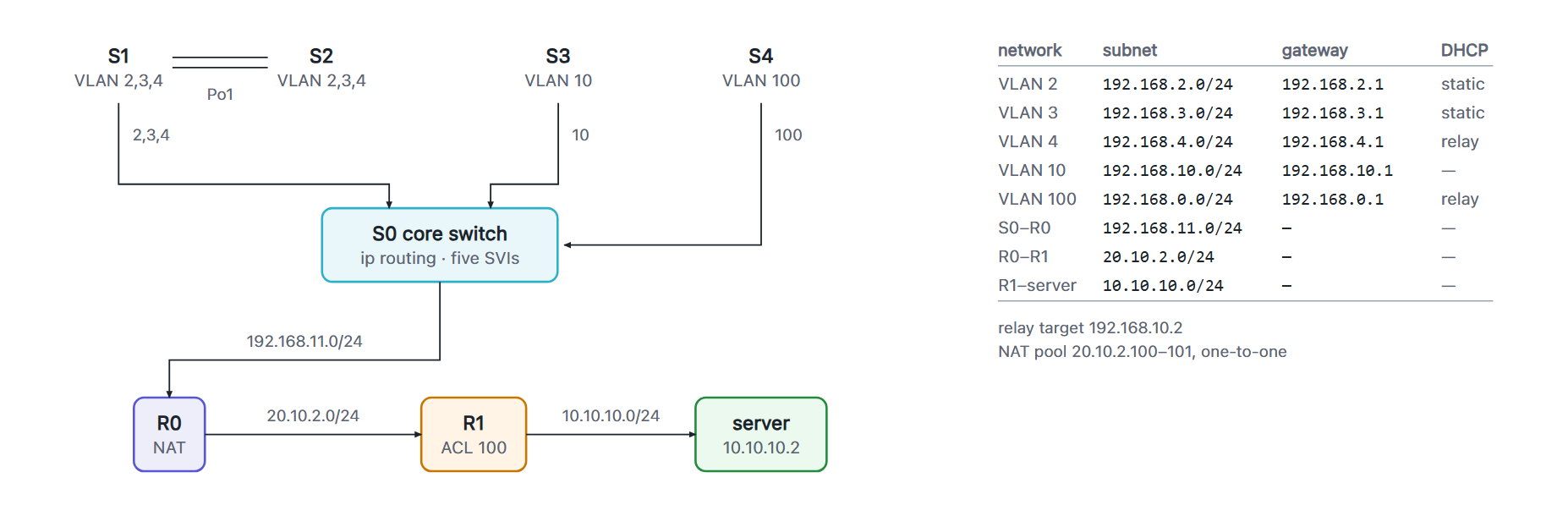
A small enterprise network built in Cisco Packet Tracer: five VLANs behind a layer-3 core switch, an EtherChannel-trunked access layer, RIPv2 between two routers, NAT to an outside network, a wireless VLAN and an access list, built as coursework in 2025. The topology file and the exported device configurations are in the repository, under MIT.
After the build I audited the exported configurations line by line and worked through five findings, including one that explains why a filter placed after address translation can never match the address it was written for.
The problem
The brief was a campus-scale network with the usual services: separate user, management and wireless VLANs; redundancy between access switches; routing between VLANs; address translation to an outside network; and a filter that keeps one VLAN away from one server. The interesting constraint is not any single service but where each one lives. Put inter-VLAN routing on a router and every packet between two desks crosses a slow link twice; put the filter on the wrong side of the NAT boundary and it filters nothing. The design decisions are placement decisions.
Design
Every routed service is in a different place on purpose, so each can be examined on its own:
| Service | Where | How |
|---|---|---|
| Inter-VLAN routing | Core switch S0 | ip routing with an SVI per VLAN, so traffic between VLANs never leaves the switch |
| Link redundancy | Access switches S1 – S2 | Two ports bundled as Port-channel 1 (mode on), carrying a trunk; PVST sees one logical link and has nothing to block |
| DHCP | Relayed from S0 | ip helper-address on the VLAN 4 and VLAN 100 SVIs, pointing at a server in the management VLAN; VLANs 2 and 3 are static by design |
| NAT | Border router R0 | Five private ranges translated onto a two-address pool, one-to-one, no overload |
| Filtering | Outside router R1 | Extended ACL 100, outbound on the server-facing interface, meant to block VLAN 2's HTTP to 10.10.10.2 |
| Dynamic routing | R0 ↔ R1 | RIPv2, no auto-summary |
Two decisions carry through the whole configuration. Each trunk allows only the VLANs it needs, so
a link's allowed list is a statement about what is supposed to cross it rather than a default. And
the uplink from S0 to R0 is a routed port (no switchport) rather than yet another
VLAN — a point-to-point subnet, 192.168.11.0/24, which puts the boundary between
switching and routing where a reader of the configuration can see it.
Following one packet
The clearest way to read the design is to take one frame and watch what each device does to it. Three journeys cover the whole topology, and each of them stops at a different layer.
Desk to desk, same VLAN. A frame from one host in VLAN 2 to another leaves the
access switch, crosses the EtherChannel to its neighbour if the destination hangs off the other
switch, and is delivered. It is switched the whole way and never reaches a routed interface. The
bundle is what makes this path survive a cable: PVST sees Port-channel 1 as one
logical link, so there is no second port for it to block and nothing to reconverge when one member
drops.
Desk to desk, different VLAN. A frame from VLAN 2 to VLAN 3 goes to its
gateway, which is the Vlan2 SVI on the core switch S0. S0 routes it and sends it
straight back out on VLAN 3. It never touches a router, and that is the whole reason
inter-VLAN routing lives on the core: put it on R0 instead and every packet between two desks
crosses the uplink twice.
Desk to the outside server. This is the long path, and it crosses every boundary in the design:
- A host in VLAN 2, source 192.168.2.10, sends to 10.10.10.2. Its gateway is the
Vlan2SVI on S0. - S0 routes it. The destination is in none of its five connected subnets, so it takes the default route out of the routed uplink — 192.168.11.0/24, a point-to-point subnet rather than a sixth VLAN, so the packet is visibly leaving the switched domain at this hop.
- R0 receives it on the
nat insideinterface, matches the translation list, and rewrites the source to 20.10.2.100 from the two-address pool. The packet that leaves thenat outsideinterface no longer carries the address it arrived with. - RIPv2 has given R0 a route to the server subnet through R1, so it forwards; R1 delivers onto its connected 10.10.10.0/24 and applies ACL 100 outbound on the way.
Steps 3 and 4 are the pair worth reading together, because the packet that reaches the filter is no longer the packet that left the host. That is what the audit in the next section is built around.
Auditing the configuration
I audited the exported configurations line by line after the build. The repository's
config/ carries the corrected versions, and one case is kept as built with the
reasoning written into the file as a comment, because it is the most instructive path in the
whole topology.
| # | Finding | Effect | Status |
|---|---|---|---|
| 1 | ACL 100 had a single deny and no permit |
The implicit deny ip any any dropped all traffic leaving R1's server interface, not just VLAN 2's web traffic |
Fixed—one line |
| 2 | ACL sits downstream of NAT | The deny can never match; see below | Left in place, documented |
| 3 | R1 carried a dead copy of R0's NAT block | Never consulted—no interface on R1 is marked inside/outside—but misleading to anyone diffing the routers | Removed |
| 4 | No route between S0 and R0 | S0 had no default route; R0's five RIP network statements matched nothing directly connected and advertised nothing. NAT sessions still appeared to work because the translation table carried replies back |
Static routes added on both |
| 5 | Duplicated interface stanza on R1 | Cosmetic; IOS merges them | Merged |

Where a filter has to sit relative to NAT
ip access-list extended 100
 deny   tcp 192.168.2.0 0.0.0.255 host 10.10.10.2 eq www
 permit ip any any
Even with the permit added, the deny never fires. R0 translates every
internal source into the 20.10.2.100–101 pool before forwarding to R1. By the time a
packet reaches R1, its source is 20.10.2.100, and a rule matching on 192.168.2.0/24 has nothing to
match against. There is no error and no log entry; the rule simply does nothing.
The fix is to move the filter, not edit it: inbound on R0's inside interface, before translation, where the real source addresses still exist. Filter as close to the source as possible, and always before NAT.
Findings 1, 2 and 4 all sit on the same path, which is why a single "can VLAN 2 reach the server" check cannot tell them apart. That is the reason the repository ships a verification order rather than a checklist.
How I isolated it
Three of the findings sit on the same path, so a single “can VLAN 2 reach the server” test cannot tell them apart. I separated them by choosing a test that only one of them could explain.
Reachability first: a ping from a VLAN 2 host to R0 isolates the missing default route on S0, because
nothing downstream is involved yet. Translation next: show ip nat translations lists an
entry even when the ping never completes, which separates “NAT is working” from “the
destination is reachable”; running pings from three hosts at once against a two-address pool shows
where that pool runs out. The filter last: in Simulation mode I stopped a packet at R1 and read its
source address, 20.10.2.100, which is the whole explanation—the rule was written for an address
that no longer exists at that point in the path. Moving it inbound on R0 confirmed it.
The .pkt file is kept exactly as built, so the original behaviour is still there to walk
through.