Electronic Circuit Design
Five circuits built between 2022 and 2024, each carried the whole way from a first sketch to a schematic, a simulation and a board: an eight-way quiz buzzer in 74-series logic, a running-light music circuit, a sound-and-light alarm, an AT89C51 countdown timer, and an STM32 interrupt study. The first three hold their behaviour in the wiring; the last two move it into firmware, once by polling and once by interrupt.
Eight-way quiz buzzer
Eight contestants, one button each, and a host's control switch. The first button pressed has to be identified, its number latched and shown on a seven-segment display, a short tone sounded, and every other button locked out until the host clears the round. A countdown runs alongside it and ends the round when it reaches zero.
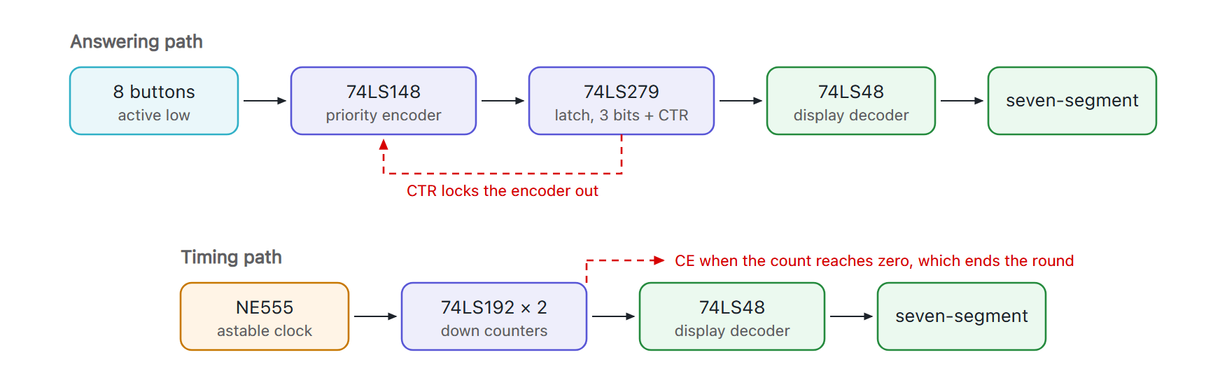
The buttons are active low, each pulled up and taken to ground when pressed, and each passes through a debounce stage before it reaches the logic. A 74LS148 priority encoder turns eight lines into a three-bit number, which is what makes two simultaneous presses resolve to one answer instead of a wrong code. A 74LS279 latch holds those three bits and, in a fourth cell, a flag called CTR that says a number is held. CTR is the whole design: it drives the enable on the encoder, so the instant a number is latched no further press can reach it, and the number stays on the display until the host's reset clears the latch.
Display comes from a 74LS48, and the small amount of glue between the stages is 74LS00 and 74LS04. The countdown is a pair of 74LS192 down counters preset by the host's start signal, clocked by an NE555 astable at 10 kΩ, 10 kΩ and 0.47 µF, running through a second 74LS48 to its own display; reaching zero raises CE, which ends the round the same way a press does. Power is four cells at 6 V brought down to the 5 V the logic wants.
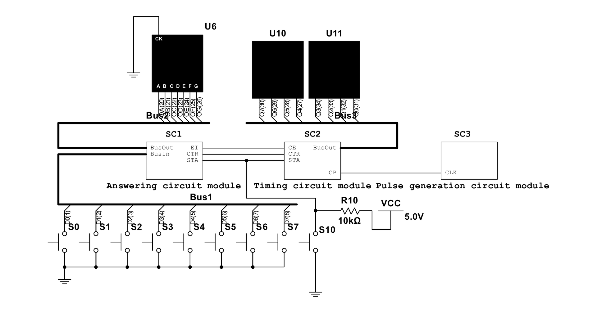
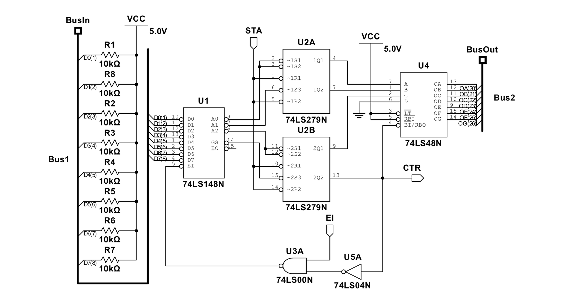
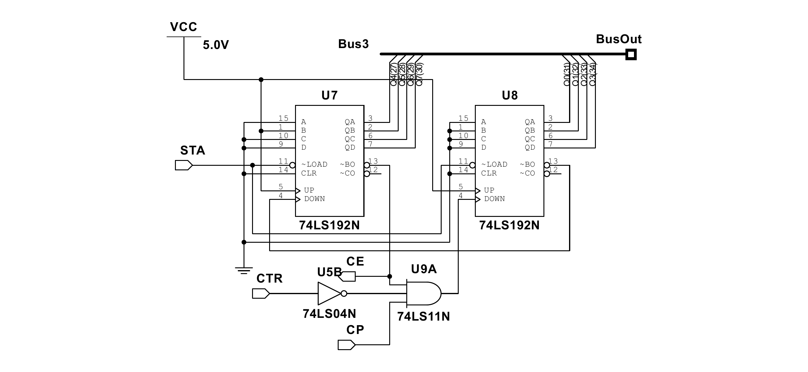
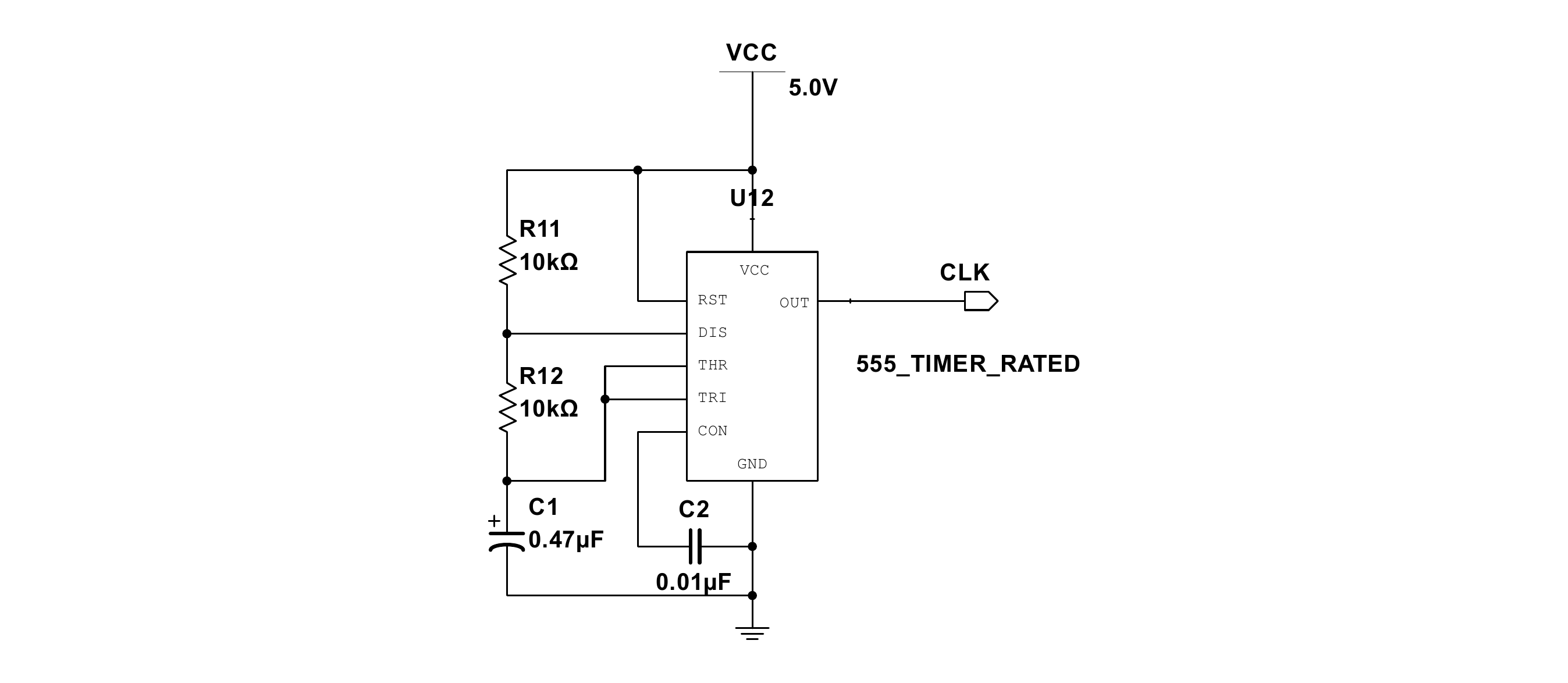
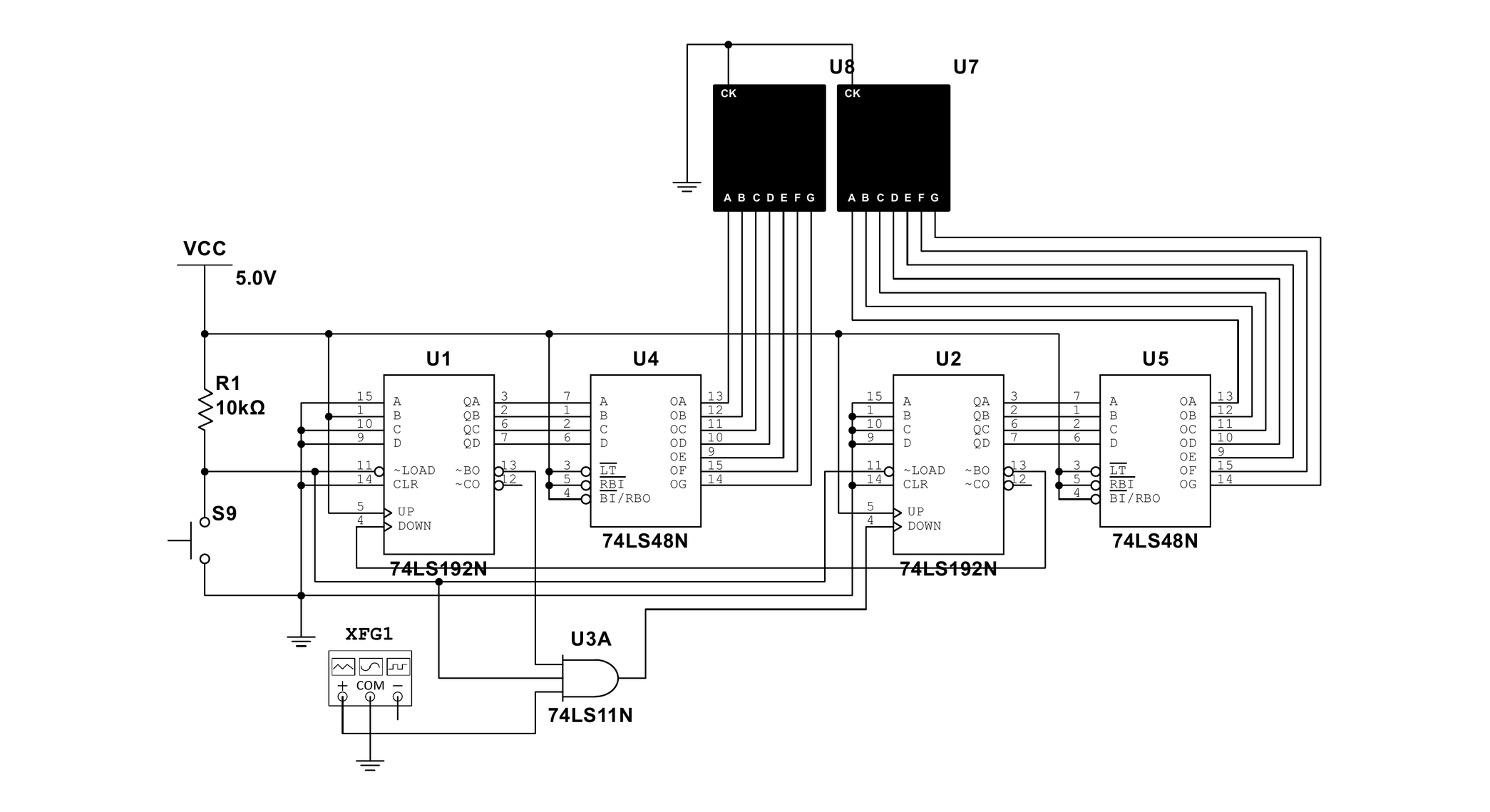
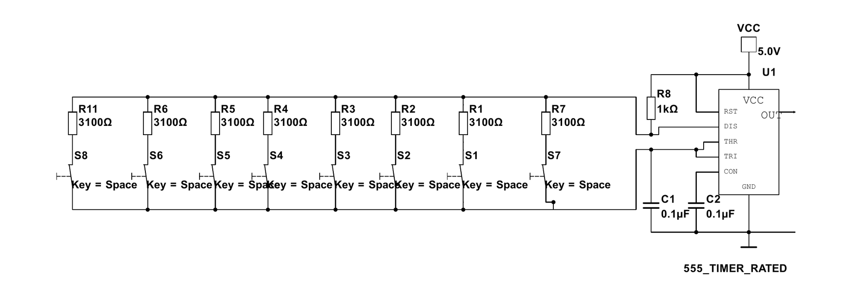
Each block was drawn and simulated on its own before the whole circuit was put together, and only then was it built and tested on a board. Splitting it that way is why a fault found during assembly could be traced to one sheet instead of to the whole schematic.
Running-light music circuit
A 555 in the astable configuration, and a decade counter behind it. Each pulse moves the CD4017 to its next output, so exactly one of ten LEDs is lit at any moment and the lit one walks along the row. The same pulse train drives a speaker, so the light and the tone are one signal seen two ways—change the timing resistors and both change together, which is what makes it a circuit rather than ten LEDs on ten pins.
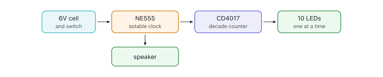
The rate is set in one place. The 555 charges its timing capacitor through both resistors and discharges it through one, so the two resistor values and the capacitor between them fix the period and the duty cycle together; nothing else in the circuit has a say. The CD4017 then does the only arithmetic on the board—it advances one step per rising edge and holds exactly one of its ten outputs high, so “one LED at a time, in order, forever” is a property of the part rather than something the circuit has to arrange.
That is what makes the two outputs stay related. A version with a microcontroller would have a variable for the light and a variable for the tone, and keeping them in step would be a thing the firmware had to do correctly. Here they are the same signal taken from the same node, so they cannot disagree.
Sound-and-light alarm
The same part in the same configuration, asked for something else. The 555 output goes to two transistors instead of a counter: an 8050 NPN sinks the buzzer, an 8550 PNP switches a pair of indicator LEDs. One is turned on by the high half of the cycle and the other by the low half, so sound and light alternate from a single oscillator and no second timing element is needed.

The complementary pair is what does the work. The NPN sits below the buzzer and conducts when the 555 output is high, pulling the buzzer's low side to ground; the PNP sits above the LEDs and conducts when the output is low, so the two loads are driven by opposite halves of one cycle. Neither device is asked to do anything but switch, and the transistors are there because the 555 can decide the state of a load but cannot supply its current.
Both circuits were carried to a finished board: schematic, layout, and—because several of the parts were not in the stock libraries—a symbol and footprint library of my own, drawn from the datasheet dimensions so the pads match the parts that would actually be soldered to them.
Countdown timer
The fourth is the same kind of problem answered a different way. An AT89C51 runs a settable countdown timer: six buttons set it, start it, pause it and reset it, an LCD shows the time, and a buzzer sounds when it reaches zero. What the 74-series version needed a sheet of logic for is a few lines of firmware here, and what the hardware has to provide instead is a clean interface.
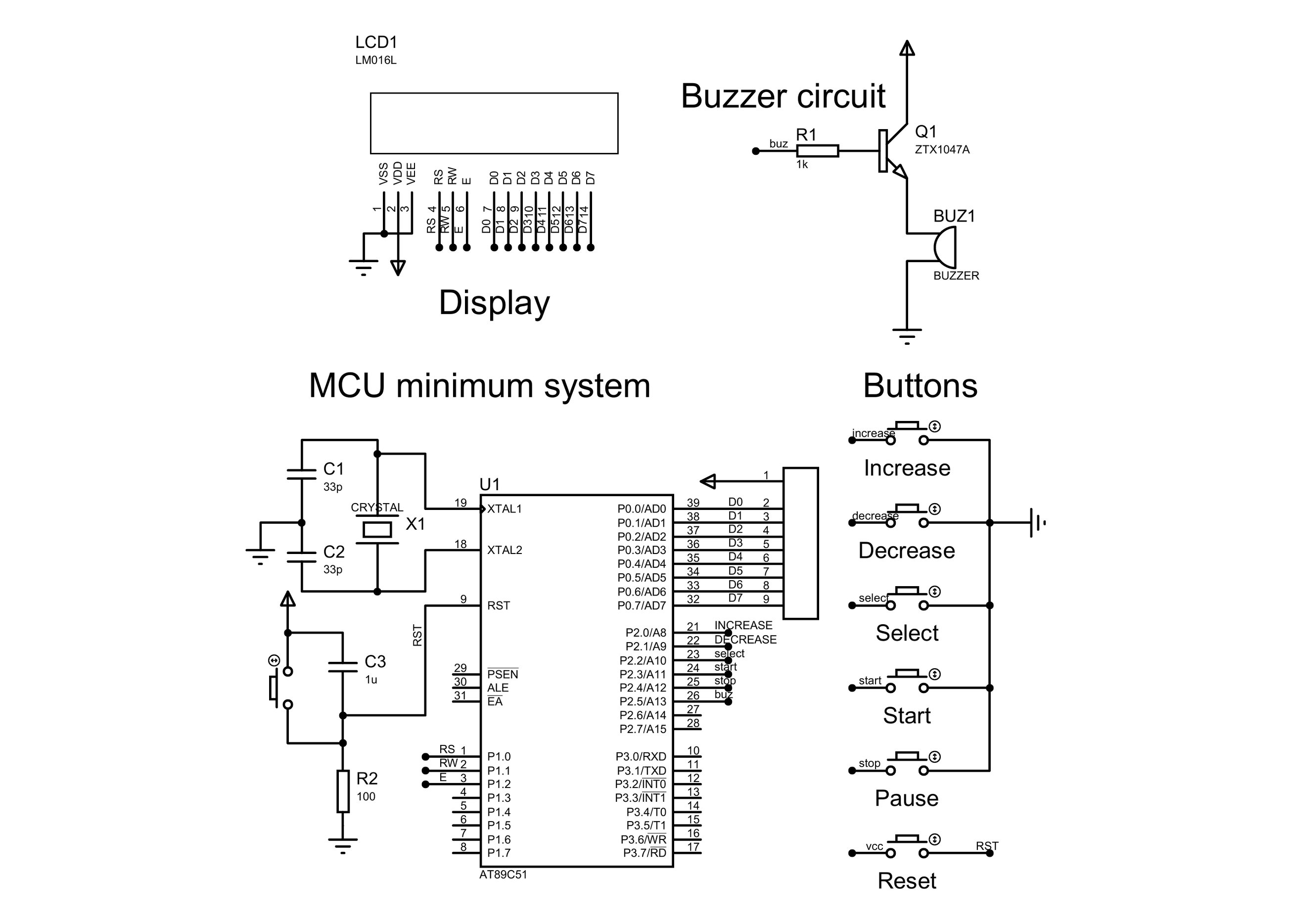
The sheet is divided the way the other three are: display, buzzer, minimum system, buttons. The minimum system is the part that is always the same—crystal with its two load capacitors, a reset network, the supply—so drawing it as its own block means it lifts into the next 8051 project unchanged. The LCD takes its eight data lines from P0 and its three control lines from P1; the six buttons come in on P2; the buzzer hangs off one more P2 pin through a resistor into a transistor, because the pin can switch it but cannot drive it.
The firmware is split the way the hardware is. The AT89C51 has hardware timers and no display controller, so one timer owns the second—it interrupts at a fixed rate and the handler does nothing but decrement the count—while the main loop owns the LCD and the buttons. Nothing in the main loop can lengthen a second, and nothing in the interrupt has to wait for a character to finish writing.
What is left is a small amount of state and the rules that move it: whether the timer is running, what the count is, and which field the setting buttons act on. Select chooses the field, increase and decrease move it, start and pause flip the running flag, and reset restores the set value. Six buttons on shared port pins mean six contacts that bounce, so a press is only accepted once the line has been stable across successive passes of the loop—the same discipline the FPGA lock applies in hardware, done here in software because here it is the cheaper place to put it. The display is written only when the value it shows has changed, which keeps a 1602's slow character writes out of the path that has to notice the next press.
STM32 external interrupts
The fifth changes the part and the mechanism at the same time. An STM32F103C8 drives twelve LEDs on PA1 to PA12 and takes three buttons on PB0 to PB2, and the buttons are not polled: each is an external interrupt line into EXTI, prioritised by the NVIC.
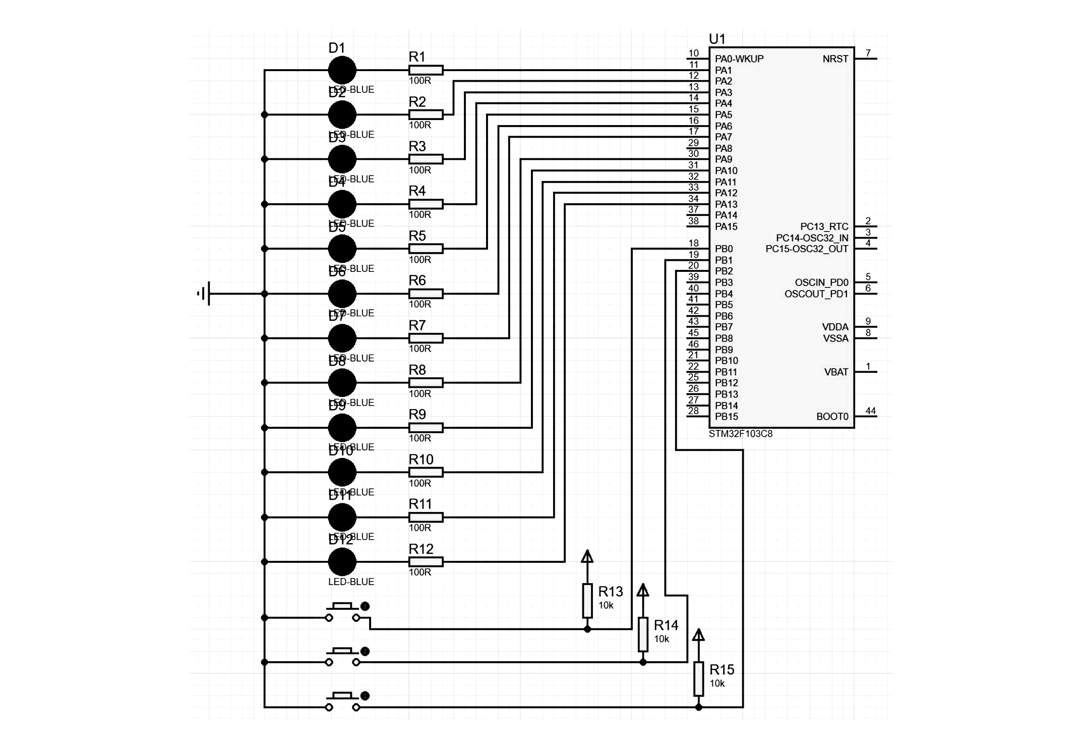
One button steps through six blink patterns, one changes the interval between 100 ms and 1,000 ms in 100 ms steps, and one selects which single LED blinks. The reason to do it on interrupts rather than in a loop is the same reason the FPGA lock keeps its scanner separate: the thing that produces the light pattern should not have to keep asking whether a button has been pressed. The pattern runs; a press arrives when it arrives.
The hardware around it is the minimum the mechanism needs. Each LED has a 100 Ω resistor, so the pin sets the state and the resistor sets the current. Each button pulls its line to ground against a 10 kΩ pull-up, which is what gives EXTI a clean falling edge to trigger on.
The firmware follows the same separation. A handler runs at interrupt priority, so it does the least it can: it changes one variable—which pattern, which interval, which LED—and returns. Everything that takes time, the pattern itself and the delay between steps, stays in the main loop and reads those variables on its next step. A press therefore takes effect at the next boundary of the pattern rather than in the middle of it, and the pattern never has to ask whether a button has been pressed.
Three lines and one NVIC priority order are what the mechanism costs, and what it buys is that the three inputs are independent of each other and of the output. Polling would have made the response time to a press a function of how long the current blink step happens to be—which is the kind of coupling this study was written to remove.